Making Stuff with Arduino
Nick Borko
May 11, 2013

Except where otherwise noted, this work is licensed under
http://creativecommons.org/licenses/by-nc-sa/3.0
Go Straight to the Project
Agenda
- Introduction
- What is a microprocessor?
- What's so great about the Arduino?
- History of the Arduino
- Overview of the Arduino hardware
- Overview of the Arduino IDE
- Overview of Arduino programming
- From Prototype to Gadget
- Our Project: The Chiptune Player
What is a Microprocessor?
There are 5 basic functions units of a computer system:
- Control Unit (CU)
- Arithmetic-Logical-Unit (ALU)
- Memory (ROM, RAM, Registers)
- Input
- Output
What is a Microprocessor?

What is a Microprocessor?
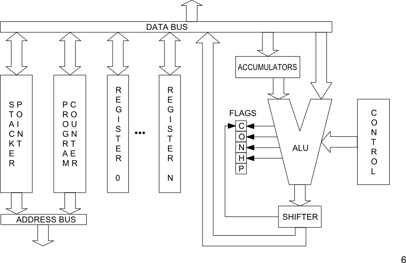
- The classical definition of a microprocessor is the combination of the Control Unit, Arithmetical-Logical-Unit and Registers in a single package, a.k.a. CPU
- Modern microprocessors also integrate input and output ports and on-chip memory (cache, EEPROM, flash, RAM)
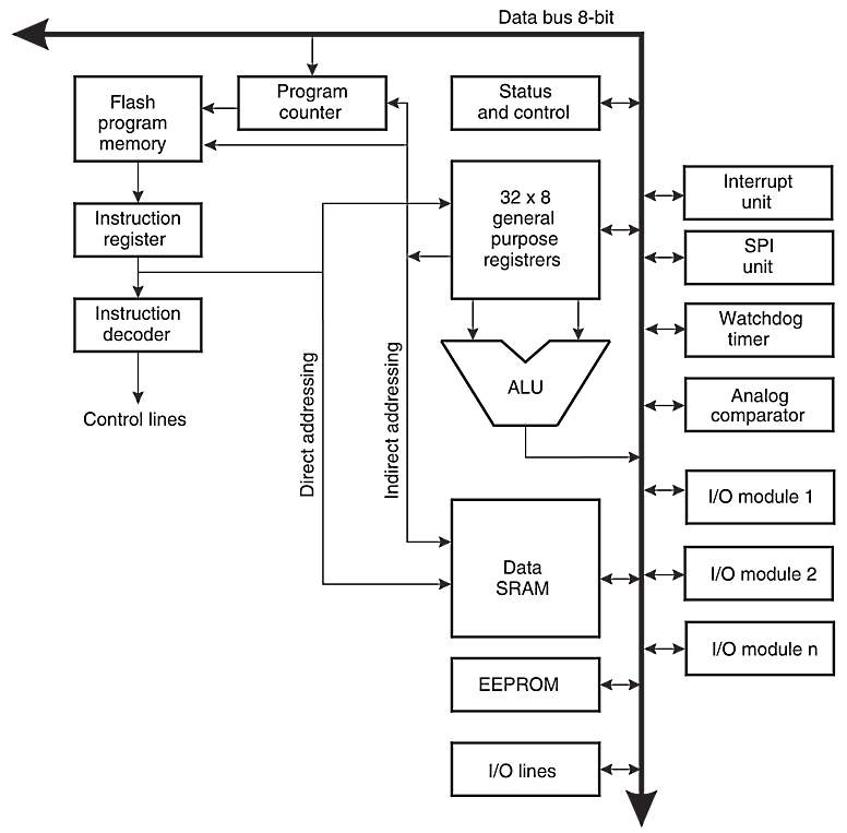
- The Arduino is controlled by a microprocessor called the AVR
General Microprocessor
Architecture (8080, 6502)
Atmel AVR Architecture
© Atmel Corporation
What's so great about the Arduino?
Arduino isn't just hardware, it's a complete development environment:
- An open-source electronics prototyping platform based on inexpensive hardware
- A free, easy to use software integrated development environment (IDE)
- A familiar programming language based on Processing and C/C++
- An active, diverse, inclusive development community
History of the Arduino
- Developed by Massimo Banzi and David Cuartielles at the
Interaction Design Institute Ivrea, Italy in 2005
- Designed to be an inexpensive prototyping system for student interactive design projects
- Built upon the Wiring Platform, by Hernando Barragán, based on the AVR and Processing
- See the full length documentary video at http://vimeo.com/18539129
Arduino Hardware Overview
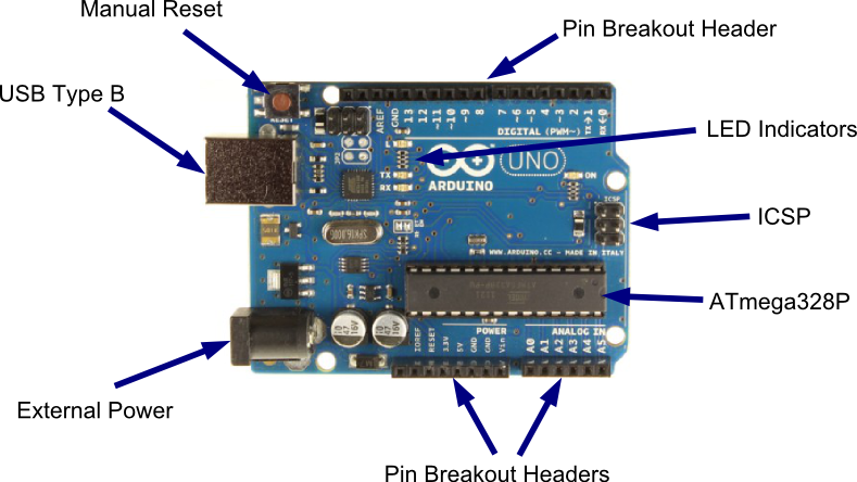
- Based on the Atmel Atmega168/328[P], an 8-bit AVR running on 5V at 16MHz
- Programmed with a bootloader to bootstrap loading programs from USB
- Microprocessor pins are broken out to headers in a standard configuration
- Additional “shield” boards can be “stacked” on the headers for extended functionality
Arduino UNO R3 (~$30)
Arduino IDE Overview
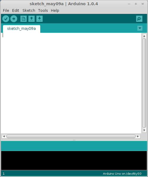
- The Arduino IDE (Integrated Development Environment) is all you need to develop programs for the Arduino
- Written in Java, based on the Wiring IDE
- Runs on Windows, OSX and Linux
- Automates the entire AVR development toolchain: editor, compiler/linker (avrgcc), uploader (avrdude), terminal emulator, and more
Arduino IDE (1.0.4)
Arduino Programming Overview
- The Arduino programming language is actually C++, written on top of the Arduino Core
- A programmer doesn't have to know how to write C++ programs, only the conventions for writing Arduino programs
- The Arduino IDE takes care of compiling, linking and uploading the program, so you don't have to know how to use any of those tools
What is the Arduino Core?
- The Arduino Core provides the main entry function, data types, and high level functions to program the AVR
- It is a library that abstracts low level microprocessor programming concepts into high level function calls
- It is based on Processing, a language designed to teach programming in a visual context to non-programmers
What is the Arduino Core?
- The Arduino Core assigns a set of standard numbers to the generic I/O pins of the microprocessor for use in programs
- The Arduino Core is automatically included in and linked to your Arduino programs
- You can extend the Arduino Core with regular C and C++ libraries
What is the Arduino Core?
A basic AVR program to blink a LED (in C):// http://hackaday.com/2010/10/25/avr-programming-02-the-hardware/
#include <avr/io.h>
#include <avr/interrupt.h>
int main(void) {
//Setup the clock
cli(); //Disable global interrupts
TCCR1B |= 1<<CS11 | 1<<CS10; //Divide by 64
OCR1A = 15624; //Count 15624 cycles for 1 second interrupt
TCCR1B |= 1<<WGM12; //Put Timer/Counter1 in CTC mode
TIMSK1 |= 1<<OCIE1A; //enable timer compare interrupt
sei(); //Enable global interrupts
DDRD |= (1<<0); //Set PortD Pin0 as an output
PORTD |= (1<<0); //Set PortD Pin0 high to turn on LED
while(1) { } //Loop forever, interrupts do the rest
}
//Interrupt Service Routine
ISR(TIMER1_COMPA_vect) {
PORTD ^= (1<<0); //Use xor to toggle the LED
}What is the Arduino Core?
A basic Arduino program to blink a LED:void setup() {
// initialize the digital pin as an output.
// Pin 13 has an LED connected on most Arduino boards:
pinMode(13, OUTPUT);
}
void loop() {
digitalWrite(13, HIGH); // set the LED on
delay(1000); // wait for a second
digitalWrite(13, LOW); // set the LED off
delay(1000); // wait for a second
}Advantages of the Arduino Core
- You don't have to write boilerplate code usually required for microprocessor programming
- Interaction with microprocessor functions is done through high level function calls rather than looking up bits to set in registers from a data sheet
- Code is readable and understandable by humans, even by non-programmers
From Prototype to Gadget
- Create a sketch & circuit for the Arduino.
- Pick a compatible part (AVR) with the correct number of input/output pins and size, voltage, clock, etc. requirements.
- Modify sketch and input/output hardware to match capabilities of microprocessor.
- Test, refine, test... and test and test!
- Design your final board — pre-printed breadboard, etch your own, board service, or deadbug!
From Prototype to Gadget
Create a sketch & circuit for the Arduino
- Chiptune player started as an idea to create a "fuzz organ"
- See bach_multitone sketch on github:
https://github.com/nborko/vc-arduino/blob/master/bach_multitone/bach_multitone.ino
From Prototype to Gadget
Pick a compatible part (AVR)
- The chiptune player needs 2 output pins for sound and 1 for arpeggio control
- Need at least 4k of flash (for program), at least 256 bytes of RAM (main memory)
- The ATtinyx5 series has 5 input/output pins, can run up to 20MHz
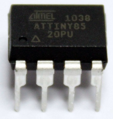
- We picked the ATtiny85 (8k flash, 512 bytes RAM, internal 8MHz clock)
From Prototype to Gadget
Modify Sketch and Hardare for Microprocessor
- Internal timers work differently, so a custom timer interrupt had to be used
- Clock is slower (8MHz vs. 16MHz), so tone generation and note timing functions had to be modified
- Desgn goals vs. compromises:
- E.g., using the internal clock minimizes parts, but speed will slightly differ from part to part
From Prototype to Gadget
Test, refine, test... (ad nauseam)
- Always test your design on a breadboard — use real parts!
- If using SMD parts, use breakout boards. In the long run it will save you time and $$
- Don't buy just one set of parts for prototype/testing, have 3-5 sets on hand, more if a part is easily lost, broken, burned, bricked...
- It's OK to go back to the drawing board if things aren't working out
- Always expect the unexpected!
From Prototype to Gadget
Design Your Final Board
- Keep in mind issues like utility, size, longevity
- Ugly but functional is better than pretty but disposable
- Design services are nice and getting cheaper, but pre-printed breadboards are cheap and available
- Don't be afraid to try something different!
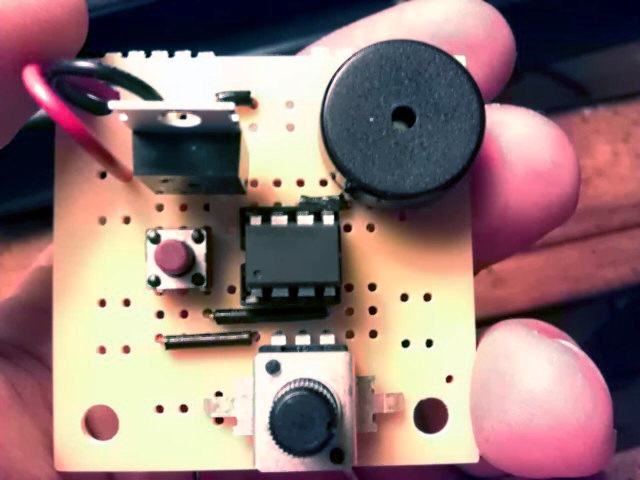
Our Project: A Chiptune Player
- Plays synthesized 8-bit music
- Prototyped on a standard Arduino Uno
- Built to spec using an ATtiny85
Chiptune Player Schematic

Chiptune Player Code
- Code can be found on github:
https://github.com/nborko/vc-arduino - Warning: Code is more AVR than Arduino, but the Arduino core is still being used
The Microprocessor
Atmel ATtiny85 AVR
The Parts

Soldering Is Easy
- This project requires soldering
- Don't worry, soldering is easy!
- http://mightyohm.com/files/soldercomic/FullSolderComic_EN.pdf
The Build
Step 1: The (Almost) Empty Board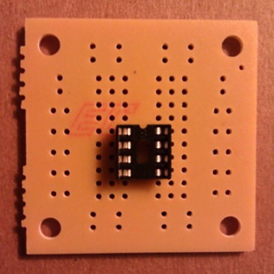
The Build
Step 2: The Jumpers (Wires)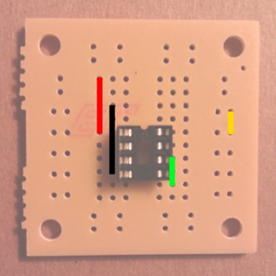
The Build
Step 3: The Piezo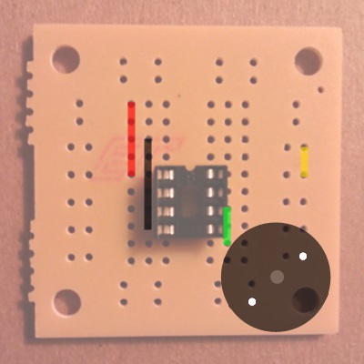
The Build
Step 4: The Push Button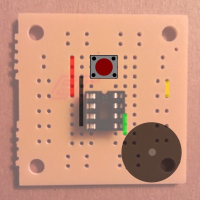
The Build
Step 5: The Potentiometer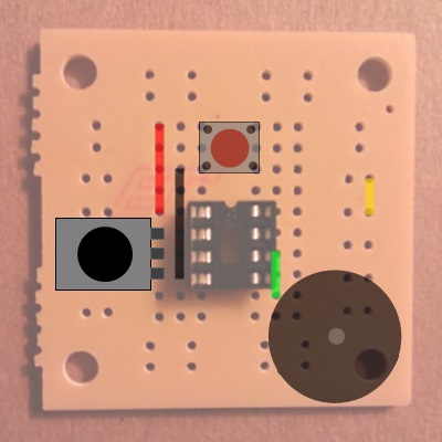
The Build
Step 6: The Regulator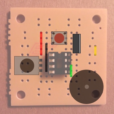
The Build
Step 7: The Battery Snap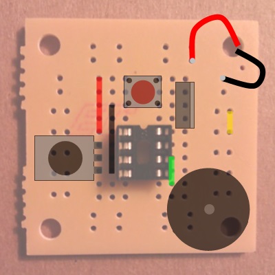
The Build
Some helpful hints:
- Bend wire and part leads out to hold them in place.
- Solder lower profile parts first, bigger parts last.
- Use clamps, clothespins or even gravity to help hold the parts close to the board before soldering.
- Run the battery snap leads from the bottom of the board up through the corner hole and back down on the board again. This will help relieve tension on the solder joint.
- Have fun!
This presentation is available online at:
http://nborko.github.io/vc-arduino/
All source files used for this workshop are available online at:
https://github.com/nborko/vc-arduino
 Making Stuff with Arduino
Presented by Nicholas Borko